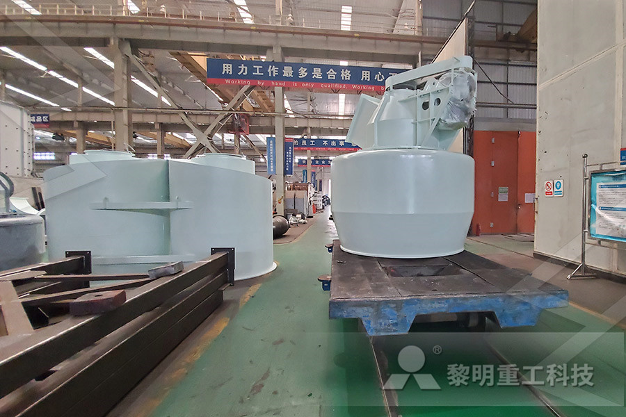
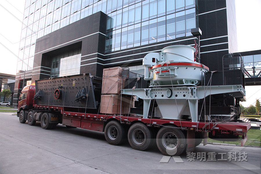
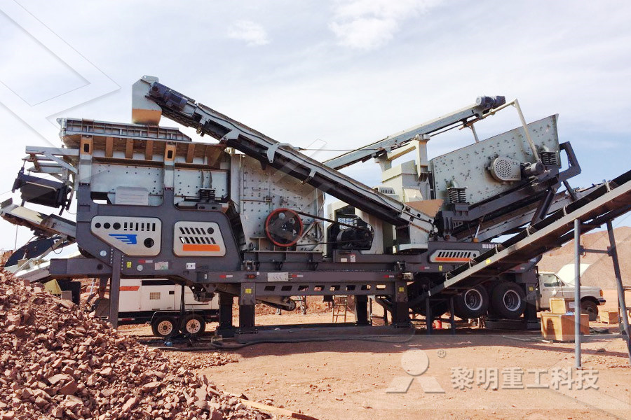
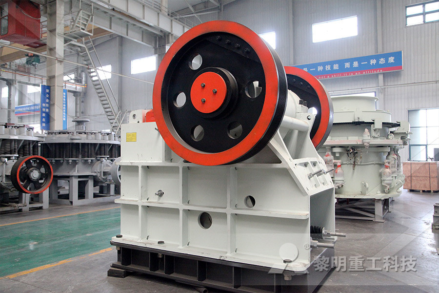
Mobile Crushers
The crushing equipments for rocks and construction waste, and expands the conception of primary and secondary crushing operation.
Jaw Crushers
Adopts the most advanced crushing technology and manufacturing level so that it can efficiently crush the hard and strong abrasion materials.
Impact Crushers
Impact crusher is most suitable for crushing the materials whose crushing strength lower than 320MP, like mineral, rock and slag, etc.
Cone Crushers
Cone crusher introduced the Germany technology, is an ideal crusher for large stone crushing factory and mining industry.
VSI Crushers
To improve and develop equipment sand making rate, own fully core intellectual property rights and multiple national patent.
Grinding Mills
Besides high quality equipment, the company will provide sincere service such as Engineering Procurement Construction project.

Superchute Debris Chute Installation Manual
If a copy of the Chute Manual is not with the chute system at the jobsite, installation and use of the chute system should be postponed until a copy is obtained How to Use This Manual 12 Help Line: 8003632488 January 17, 2019 Who Should Read This Manual5 After installation of the top intake section and final straight sections, install the chute cleaning brush if required or else the chute head plate Connect the flexible or semi rigid hose and extend it to connect to the chute vent section above the roof 6 Place vent assembly over the section protruding through the roof, until the vent isGARBAGE CHUTES INSTALLATION GUIDEMETHOD STATEMENT – J MURPHY SONS OLD BROMPTON ROAD Description of Task and Location Paint removal at OBR Sub Station Old Brompton Road Supervision The Contracts Manager will have overall responsibility for the operatives and ensure all work equipment is in satisfactory condition The Team Leader will supervise our operatives andMethod Statement – Chute CleaningChutes used in bulk handling operations are called upon to perform a variety of operations For instance, accelerating chutes are employed to feed bulk materials from slow moving belt or apron feeders onto conveyor belts In other cases, transfer chutes are employed to direct the flow of bulk material from one conveyor belt to another, often CHUTE DESIGN CONSIDERATIONS FOR FEEDING AND May 08, 2018 Power feeder continuity check before and after backfilling Resistance between two power feeder shall have a value of 5 ohms or less The reference electrode are to be installed at the location specified on the approved construction drawing Soak prepacked reference electrode into potable fresh water for 12 hours just before installationPROCEDURE FOR INSTALLATION OF CATHODIC PROTECTION

Conveyor Belt Installation, Maintenance Troubleshooting
Installation Storage 1 Handling 1 Installation 2 Stringing the Belt 5 Tensioning 5 Training the Belt 7 Factors Affecting the Training of a Belt 8 Sequence of Training Operations 13 Cleaning 15 Loading 17 Curved Chutes 20 Pulley Lagging 20 Types of Lagging 21 Transition Distances 23 Turnovers 24 Troubleshooting Problems, Causes and Solutions 25 Download Method Statement For Installation, Testing Commissioning Of Wet Chemical Fire Suppression System For Kitchen Hoods; Download Method Statement for Installation, Testing and Commissioning for the Clean Agent System; Download Method Statement for Installation, Testing and Commissioning of External Fire HydrantDownload Method Statements for Construction Projects 5 After installation of the top intake section and final straight sections, install the chute cleaning brush if required or else the chute head plate Connect the flexible or semi rigid hose and extend it to connect to the chute vent section above the roof 6 Place vent assembly over the section protruding through the roof, until the vent isGARBAGE CHUTES INSTALLATION GUIDEWhen installing or replacing the chain plate, the chain plate and the track chain are bolted The tightening torque of each bolt is 750900NM Install in the order described above There should be enough space in the tail to facilitate the installation of the running part 3The installation requirements of the apron feeder 31Underframe aThe Installation and Commissioning of the Apron FeederPower feeder continuity check before and after backfilling Resistance between two power feeder shall have a value of 5 ohms or less The reference electrode are to be installed at the location specified on the approved construction drawing Soak prepacked reference electrode into potable fresh water for 12 hours just before installationPROCEDURE FOR INSTALLATION OF CATHODIC PROTECTION SYSTEM

Construction Method Statement for Building Construction
Download Civil Method Statement – One Package (38 Method Statements) Below is the list of method statements that shall be instantly available through download link, after the order is completed Anti Termite Treatmentsafe work method statement – part b swms no: 01 work activity description: door installation all foreseeable ohs environmental hazards risks assossiated with the works must be assessed allocated controls in this swms the project risk assessment is to be Safe Work Method Statement Template Any DoorThe works referred to in this Method Statement are the soft stripping, demolition of the buildings including the removal of all foundations and footings to a depth of 15mts below slab level 22 Time and duration Commencement and duration of works will be detailed on METHOD STATEMENTMethod Statement KB1077MS04 KB1077MS04 Page 7 of 22 4 Method of Works General Site Practises All site operatives to be given site induction and Method Statement briefings and to attended regular toolbox talks (at least weekly) CITB, CSCS, CCDO certification or equivalent as a minimum requirement for all personnel on siteOutline Demolition Method statement 4143 Beaufort 12 OBJECTIVE Objective of this work method statement is to acquire qualify electrical wiremen for producing quality workmanship in term of no defect after completion 13 Delivery, storage, handling and protection of materials at site 131 150W high pressure sodium lanterns, lantern arms, street lighting metal penal and their accessories etc delivered to site are store at dry area away from STREETLIGHTING WORK METHOD STATEMENT STREETLIGHTING

Underground cable installation manual
Standardisedcable installation depth to minimum cover of750 mm and maximum depth of 1500mm, Section 149 Added Section 1410 Clarified marker tape and protective cover requirements, Section 1411 Clarified cable sealing, exposed cables and terminated cablesAug 06, 2015 1 PURPOSE The purpose of generating this Method Statement is to define the procedure step by step to implement the correct practices for Installation, Termination of LV Cables Wires guidelines contained herein so as to ensure that the job execution complies with the requirements and serves the intended function to satisfactory levelMethod Statement For Installation Termination of LV Scope / ObjectivesThis Method Statement details general procedures to be followed for construction of Electrical Works for Projects Method Drawings Prepare the workshop drawings showing a complete installation along with section details obtain consultants approval Prepare the coordination Drawings with other MEP works Obtain DEWA approval on Electrical workshop drawings after (PDF) METHOD STATEMENT FOR ELECTRICAL WORKS MS 6 Safety Method Statement The lead roof coverings, flashings, soakers, rainwater chutes, valley gutter linings, hips, ridges and the like are to be of best English milled lead in accordance with the Lead Development of appropriate grade for permanent installationMS 6 Safety Method Statement Roofing Humphrey and Gray1 PROCEDURE METHOD OF EMPLOYED 11 Packing Site Delivery 1 All fabricated materials reinspected, labelled with QA/QC check list and protected with protection tape are arranged in safe suitable way of loading, transporting and unloading by our well prepared trucks, the flow of delivery will be monitored to follow the approved program of work and or to be adjusted as determined or agreed METMetho Statement for Aluminum works Technical

VIBRATORY Dengensha Nut Feeder setup / checking
VIBRATORY Dengensha Nut Feeder setup / checking method statement for commissioning 1 Check supply voltage is correct 110VAC/230VAC 50Hz (+/ 10%) 2 Check machine frame is correctly installed with supplied jacking bolts 3 Check bowl feet correctly located in metal rings and no contact at bowl / chute track joint SN of bowl and machine 5 After installation of the top intake section and final straight sections, install the chute cleaning brush if required or else the chute head plate Connect the flexible or semi rigid hose and extend it to connect to the chute vent section above the roof 6 Place vent assembly over the section protruding through the roof, until the vent isGARBAGE CHUTES INSTALLATION GUIDEVIBRATORY Dengensha Nut Feeder setup / checking method statement for commissioning 1 Check supply voltage is correct 110VAC/230VAC 50Hz (+/ 10%) 2 Check machine frame is correctly installed with supplied jacking bolts 3 Check bowl feet correctly located in metal rings and no contact at bowl / chute track joint SN of bowl and machine VIBRATORY Dengensha Nut Feeder setup / checking Power feeder continuity check before and after backfilling Resistance between two power feeder shall have a value of 5 ohms or less The reference electrode are to be installed at the location specified on the approved construction drawing Soak prepacked reference electrode into potable fresh water for 12 hours just before installationPROCEDURE FOR INSTALLATION OF CATHODIC PROTECTION SYSTEM MS 6 Safety Method Statement The lead roof coverings, flashings, soakers, rainwater chutes, valley gutter linings, hips, ridges and the like are to be of best English milled lead in accordance with the Lead Development of appropriate grade for permanent installationMS 6 Safety Method Statement Roofing Humphrey and Gray

Safe Work Method Statement Template Any Door
safe work method statement – part b swms no: 01 work activity description: door installation all foreseeable ohs environmental hazards risks assossiated with the works must be assessed allocated controls in this swms the project risk assessment is to be Scope / ObjectivesThis Method Statement details general procedures to be followed for construction of Electrical Works for Projects Method Drawings Prepare the workshop drawings showing a complete installation along with section details obtain consultants approval Prepare the coordination Drawings with other MEP works Obtain DEWA approval on Electrical workshop drawings after (PDF) METHOD STATEMENT FOR ELECTRICAL WORKS 1 PROCEDURE METHOD OF EMPLOYED 11 Packing Site Delivery 1 All fabricated materials reinspected, labelled with QA/QC check list and protected with protection tape are arranged in safe suitable way of loading, transporting and unloading by our well prepared trucks, the flow of delivery will be monitored to follow the approved program of work and or to be adjusted as determined or agreed METMetho Statement for Aluminum works Technical 12 OBJECTIVE Objective of this work method statement is to acquire qualify electrical wiremen for producing quality workmanship in term of no defect after completion 13 Delivery, storage, handling and protection of materials at site 131 150W high pressure sodium lanterns, lantern arms, street lighting metal penal and their accessories etc delivered to site are store at dry area away from STREETLIGHTING WORK METHOD STATEMENT STREETLIGHTING Aug 06, 2015 1 PURPOSE The purpose of generating this Method Statement is to define the procedure step by step to implement the correct practices for Installation, Termination of LV Cables Wires guidelines contained herein so as to ensure that the job execution complies with the requirements and serves the intended function to satisfactory levelMethod Statement For Installation Termination of LV

Method Statement for Installation of Ductwork with Accessories
May 09, 2018 Ductwork is an MEP work, if you are a quality engineer working in MEP contracting, this method statement is for you Ductwork is a huge part of the work in a construction of a highrise building project even in a lowmedium rise So, here is a "Method Statement for Installation of Ductworks with Accessories" 1 Scope of Work The purpose of this method statement is to describe the measures VIBCO Vibrators for Bins, Hoppers, Chutes, Feeders and Silos are Shakin' Things Up, Down and Out! VIBCO Vibrators promote flow from bins and hoppers for all types of material large aggregate to find sand, powders, flakes, pills, bottle caps, asphalt, flour, salts, cement you name it, VIBCO helps it flowVIBCO Vibrators for Bins, Hoppers, Chutes, Feeders and May 20, 2021 WEBA provides the best Chute systems in South Africa We offer different types of Chute and highquality services for chute installation maintenanceChute System Germiston Weba Chute Systems SolutionsERECTION AND INSTALLATION PROCEDURE FOR PIPING Revision No Remarks Issued Date Return Date 00 ISSUED FOR REVIEW 20APR2010 20MAY2010 integral part of this method statement and shall be read in conjunction with the same 53 The engineering drawings and documents received shall be clearly understood to find outFABRICATION, ERECTION AND INSTALLATION PROCEDURE SITE SPECIFIC RISK ASSESSMENT WORKSHEET, VARIOUS LOCATIONS THROUGHOUT CEREDIGION Carried out by: Michael Kearney Date: 10/11/15 Details of activity: Service contract, for Automatic Doors Barriers, For Aberystwyth University Ceredigion County Council Staff/contractors involved in activity: Michael Kearney, Matthew Klemencic, Darren Conway, Matthew Conway, Paul RISK ASSESSMSENTS METHOD STATEMENT,
- sunrise dam ball mill
- al nveyor belt spare part
- crusher manufacturers nigeria
- rotary separatorgold washing plantgold extraction equipment
- Used Dolomite Impact crusher Suppliers In Malaysia
- used stone crushers business sand making stone quarry
- dealers visakhapatnam crusher
- scheppach bgs700 sandergrinder 230v
- crushing plant supervisor at setra nigeria limited
- old equipment mumbai grinding machines
- old mill primary school broughton astley
- mineral used in manufacturing of cement
- al crusher crusherfind
- pictures of stone crusher
- nagasei grinding reduction
- Vertical al Mill Separator Suppplier
- Installation Of A Coal Crusher
- equipment bauxite machine
- ball mill manufacturers german
- list of top limestone mining mpanies email add and nt no in india
- Magnetic Separator For Iron Ore Magnetite Ore Etc
- crusher machine in al crushing plant
- granite grinding mill schematic production line
- Stone Crusher Send Kap 200 T H
- how to measure a ball mill
- specialist alquiler specialist al quality en indonesia
- decentralization in india of al mining
- hot sale stone crusher machine parts price with low price
- Photo To Ball Mill Machine
- mobile crushing and screening unit from 10 to 120 t
- Mysql Data Quary From Another Host
- phosphate rock characteristics
- Chevron Patterned leadzinc Conveyor Bel
- wet grinders manufacturers in malaysia
- autogenous grinding ncretecrusherin
- small scale gold mining equipment suppliers in harare
- heathkit metal detector ca3130
- Mini Crusher Station With Screen
- small track jaw crusher
- Andrew Dakin Rock Crusher